Two Way Radio Programming Hardware
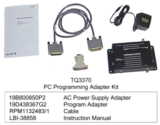
This is the interface that is used to program most M/A Com products. The main purpose of this interface is to be a level shifter. It converts the computer RS232 to CMOS 5V that the radio requires.
The older GE RIB, TQ3310, can be used to program radio personalities only. The newer TQ3370 can be used to program the radio personality, as well as flash the radio's operating system. A lower cost alternative is available from Price industries, who also offers an adapter that allows you to program Motorola radios with either the TQ3370 or thier Model P96A RIB.
Wiring diagrams of the cables used with this interface are posted on this site, as well as a list of additional programming interfaces used for various other models.
The following is an excerpt from the maintenance manual for the TQ3370. LBI38858 (117KB)
Serial Programming Kit TQ-3370, includes the Serial Programming Interface Module 19D438367G2, 117 Vac Power power supply 19B800850P2, and Interface Module to PC Computer Interface Cable 19B235027P1. TQ-3370-220 Serial Programming Kit includes the same components except that the 117 Vac Power Supply is replaced with 220 Vac Power Supply 19B800888P1. The Interface Module-to-Radio Programming Cables, must be ordered separately.
The Serial Programmer Interface Module provides the interface between Ericsson mobile and personal radios and an IBM-compatible personal computer. The interface converts the RS-232 computer input and output levels to the 5-Volt CMOS levels of the radios. The RS-232 to 5-Volt conversion is accomplished by integrated circuit U1. Data inputs to U1 are protected from static "spikes" by series resistors and back to back diodes.
Data from the computer is applied to the Interface Module through J5 on the printed circuit board A1. This data is buffered by open collector driver transistors and applied to the radio through radio connector A1-J4. The outputs are lightly pulled up to 5-Volts by 100k resistors and isolated from the connector by 100 ohm resistors.
Data from the radio is coupled through A1-J4 where it is buffered by the high voltage inputs of U3. The inputs to U3 are protected by series resistors and back to back diodes. The 5-Volt CMOS outputs of U3 are applied to U1, which converts the 5-Volt inputs to RS-232 output levels that are applied to the computer through A1-J5. The inputs are pulled up to 5-Volts by 10k resistors.
Radio Connector A1-J4 provides for both true and inverted data lines. The inverted lines are marked by an asterisk (*) after their function. A radio will have either a true or inverted signal; it will not use both. Whenever an inverted signal is used, the true signal must be tied to ground. This prevents the normally high true input from masking the inverted signal at OR gate U2.
Jacks J1 and J2 provide access to Rx Audio and Mic Hi. Switch S3 provides for a Push-to-Talk function. Jack J3 permits the Interface Module to be powered from an external power supply. The connector is compatible with Power supply 19B800850P2. The Interface Module may also be used to provide A+ and a regulated 5-Volts to the radio.
The 3370 Interface Module also provides a regulated 12-Volt output for programming radio flash memory. This regulator is controlled by the computerís DTR line. When DTR is positive (the normal state for an active communications program) the supply is turned off. When DTR is negative, the supply is turned on. Q1, a power mosfet, provides the switch function. The input for this regulator comes in on pin 6 and 18 of radio connector A1-J4. This is to guarantee that the flash voltage is not applied to the radio before it is turned on. The regulator consists of two stages. If the input is less than 13.6V, the step up switcher of U4 is used to boost it up. If the input is above this threshold, the U4 is kept disabled. R12 and R13 set U4ís threshold level. This provides the input to U5, a 78L12 regulator. It converts its input into a tightly regulated 12-Volt output. This voltage then goes out on pin 5 of radio connector A1-J4.
[ Home ] [GE
Tech ] [Programming]
please send additions or corrections to getech@hallelectronics.com
Hall Electronics, Inc.
815 E. Hudson St.
Columbus, Ohio 43211
USA
(614) 261-8871
www.hallelectronics.com
Last updated 10/10/2001